ROCOES Optical
HOME > Optical Filters
HOME
>
Optical Filters
>
Density filters/Neutral Density
Neutral Density Filters (ND Filters & Optical Attenuators)
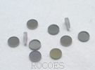
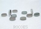
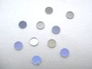
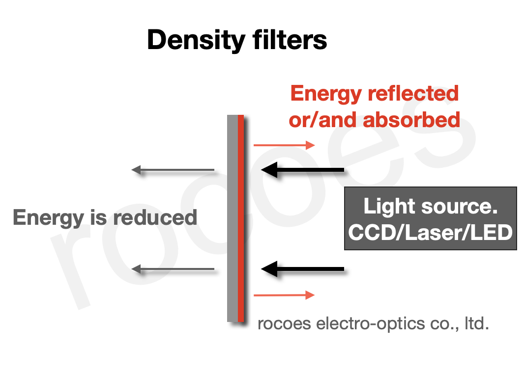
Neutral density filters (commonly referred to as ND filters, optical density filters, or light attenuators) are precision optical optics engineered to uniformly reduce light intensity across a broad spectral band without altering the relative spectral power distribution or color temperature of the incident light engine.
Functions:
Uses precision metallic alloy or thin-film dielectric absorption/reflection coatings deposited via PVD-EBGE on optical glass substrates. They provide flat, spectrally non-selective attenuation across visible ($400\text{ nm} - 700\text{ nm}$) and near-infrared ($700\text{ nm} - 1100\text{ nm}$) wavelengths. Available in discrete optical densities (ND0.3 to ND4.0, corresponding to $50\%$ down to $0.01\%$ transmittance) to prevent sensor saturation, extend exposure dynamic range, and control laser power without chromatic distortion.
Applications:
Laser power attenuation
Imaging sensor protection
Photographic exposure control
Optoelectronic detector testing
Calibration of optical measurement equipment
Automated Optical Inspection (AOI) machine vision systems
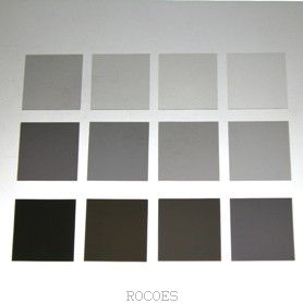
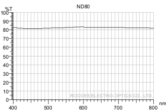
ITEM NO. ND80
Tave=80 +/-5% @420-700nm
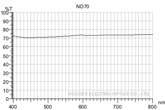
ITEM NO. ND70
Tave=70 +/-5% @420-700nm
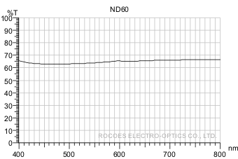
ITEM NO. ND60
Tave=60 +/-5% @420-700nm
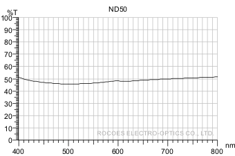
ITEM NO. ND50
Tave=50 +/-5% @420-700nm
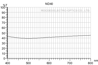
ITEM NO. ND40
Tave=40 +/-5% @420-700nm
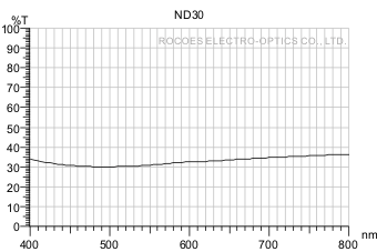
ITEM NO. ND30
Tave=30 +/-5% @420-700nm
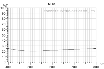
ITEM NO. ND20
ave=20 +/-5% @420-700nm
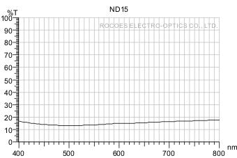
ITEM NO. ND15
Tave=15 +/-3% @420-700nm
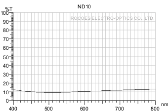
ITEM NO. ND10
ave=10 +/-3% @420-700nm
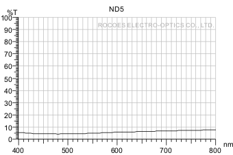
ITEM NO. ND5
Tave=5 +/-3% @420-700nm
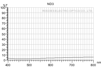
ITEM NO. ND3
Tave=3 +/-2% @420-700nm
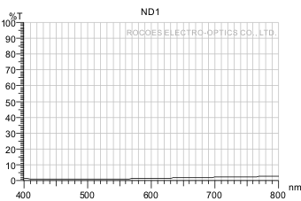
ITEM NO. ND1
Tave=1 +/-1% @420-700nm
Physical Characteristics
Glass: 1.1, 3.0mm
Square: 8x8 - 220x220mm
Round: Dia8 - 210mm
Resistant Temperature
Glass: 150℃
Information and Notes
1. Custom optical design services are available for neutral density (ND) filters, tailored to specific target optical densities or precise laser wavelength attenuation specifications (e.g., 532 nm, 635 nm, 850 nm, 940 nm).
2. Neutral density filters feature vacuum-deposited metallic thin-film alloys (e.g., NiCr, Inconel). Due to the intrinsic optical absorption and reflection properties of metallic films, total integrated transmittance and reflectance ($T + R$) will be less than 100%.
3. Vacuum thin-film depositions are executed using Physical Vapor Deposition with Electron Beam Gun Evaporation (PVD-EBGE) technology, ensuring precise optical density control, high spatial uniformity, and excellent durability.
4. Spectral transmittance curves represent physical sample measurements captured at normal incidence (0° angle of incidence, AOI). Transmittance values indicate average performance across the visible spectrum.
5. Transmittance curves reflect actual physical sample measurement data and are subject to minor manufacturing tolerances between production lots while strictly conforming to target engineering optical specifications.
6. Website specifications are for reference purposes; final product shipments adhere to the technical specifications mutually agreed upon by both parties.
7. Explore related products and technical solutions: